Thursday 25 September 2008

NXT Programming, Lesson 4


Date: 26 09 2008
Duration of activity: over 3 hours
Group members participating: all group members


1. The Goal

The goal of the lab session's work is to try to build a robot capable of balancing as well as possible.

2. The Plan

  • Analyze given examples for balancing robot

  • Rebuild Thomas to become a balancing robot

  • Adjust given source code for our robot


3. The Results

3.1. Analysis of alternative sensor options

Before our group started building a new robot for balancing, we considered other options for a sensor than the light one. As it was suggested in Brian Bagnal's book chapter [1] , a tilt sensor could have been a reasonable option as it does not depend on the environment as much as the light sensor (because of light levels or floor patterns). Unfortunately, we didn't have one and we didn't have luck finding it, so we decided to take some other option.

Next thing we considered was a rotation sensor. The idea was to measure the shift of an angle with respect to the robot's mass center. At first this seemed like a very simple and good way, to make Thomas balance, but after researching the topic we found several issues.

  • First of all the rotation sensor in the NXT set is part of the motor, and does therefore resist a manual rotation of the sensor. For this reason gravity will not be strong (fast) enough to make the rotation-counter turn and let Thomas conclude it is tilting to one side.

  • The old RCX sensors is a separate module and do not have this internal force-resistance. And unlike the pressure-sensor these are lying around in the legolab. But after further reaching into the sensor we found a cut-through picture of the sensor, which shows that the sensor only is able to count full rotations -- unlike the new NXT-model. This of course makes it unable to measure the small change in angle needed for correcting tilting.
    Lego® Rotation Sensor Internals
    It may be possible to measure angle-change to some degree, by making a big gear turn by the force of gravity turning a little gear connected to the rotation sensor. Therefore small changes in angle would make the big gear turn a little, but maybe make the little gear turn several times. This all though doesn't seem like a stable way to go.

  • And finally, after some research into the leJOS API we would out the old RTX rotation-sensor isn't even supported in leJOS NXT. Search For "RCX Rotation Sensor" on this page.


  • Because of this, we decided to make things work with the light sensor.

    3.2. Robot construction

    Our group's robot Thomas was constructed to be a two-wheeled robot with a mounted light sensor. To construct everything reasonably correctly, we have followed the instructions that were given in Brian Bagnal's book chapter [1] .

    These are the photos of Thomas new looks:


    3.1. Figure: The front of Thomas3.2. Figure: The side of Thomas3.3. Figure: The back of Thomas


    3.3. Analysis of sensor readings

    The idea of analyzing the sensor's readings was to determine the balance center of the robot. The given code Sejway.java suggests to start from the robot's balancing position, which is hard to find by hand. During the experiments with balancing, it was reasonable to hardwire a predetermined 'mass center' for the robot into the source code, for the sake of testing speed.

    This is what we got:

    3.4. Figure: Thomas goes all the way from front to back (in a linear movement) and rests a little at the balancing point.


    3.5. Figure: Thomas is balancing around the balance center.


    3.4. P I D values

    The point of all this work was to correctly adjust KP, KI, and KD values in the code to make Thomas balance by himself. These short movies show moments of robot trying to desperately balance (while is given some experimental pid values):


    4. Conclusion

    We weren't able to make Thomas balance, and the rather high number of constants to adjust made the job somewhat insurmountable and dissatisfying. Also, the theory didn't seem to apply: We could not make Thomas oscillate around the balancing point by just adjusting the P factor, as is the suggested procedure.

    We did however take the time needed to plot graphs of the tilting action, and this provided a step on the way to understanding why Thomas kept rolling over.

    5. References

    [1] Brian Bagnal, Maximum LEGO NXT, Building Robots with Java Brains


    Thursday 18 September 2008

    NXT Programming, Lesson 3


    Date: 19 09 2008
    Duration of activity: 3 hours
    Group members participating all group members


    1. The Goal

    The goal of the lesson 3 is tryout many different ideas while using the sound sensor to control the LEGO robot.

    2. The Plan

    • Mount the robot with sound sensor and tryout the test program and write down the readings.

    • Use a data logger to collect and record data in the file.

    • Try out the given program that controls the robot with different sounds and describe how the program interprets the readings.

    • Try out the idea of a ButtonListener for the escape button.

    • Carry out the suggested investigation of clapping using the parameters from Sivan Toledo.


    3. The Results

    During lab session 3 our group managed to try out everything that was suggested to do in NXT Programming Lesson 3 description, and beyond that, we were inspired by the clap controlled car idea and made some experiments regarding this type of controlling.

    • First of all, the LEGO robot (whose name is Thomas, as one may remember from previous lab descriptions) was mounted with one more sensor, the sound sensor. Thomas with the sound sensor looks like this:


      As it can be seen from these pictures, Thomas is equipped not only with the new sound sensor (the little arrow points exactly where this sensor is) but with the ultrasonic sensor and with the light sensor from previous assignments as well.

    • The next thing that we were occupied with was actually testing the sound sensor. To that end, the ideas of SonicSensorTest.java were used. Read more in 3.1. Testing sound sensor.

    • After our group was sure how the sound sensor worked, we tried to make the robot log all the readings that the sound sensor reads out. For that, DataLogger.java was used. The principle is that it writes measurements to a Sample.txt file, and this file can be retrieved using the nxjbrowse command. We changed certain things in this code to facilitate easier plotting of the measurements. Read more about this in 3.2. Data logging.

    • The next thing on the list was to try out the idea, that the robot can be controlled by sound. For that we used SoundCtrCar.java and Car.java. In this program, Thomas waits for a loud sound and then goes forwards. The next loud sound makes him go to the right, the next -- turn left and a final loud sound will make him stop. And so on, untill escape is pressed in a very peculiar way. This motivated the suggested change of the code to be ButtonListener-actuated. Read more about sound controlling in 3.3. Sound controlled car.

    • And finally, the last thing on the list was to make the LEGO robot not react to anything but the sound of clapping. For that we changed the java code as for the regular sound controlled car. What's more, we added data logging to this program as well to see if the theory corresponds to the practice. Read more about the results we got in 3.4. Clap controlled car.


    3.1. Testing sound sensor

    For testing the microphone we made some changes to the SonicSensorTest.java program, supplied on the course-homepage:

    import lejos.nxt.*;
    public class SoundSensorTest {

    public static void main(String [] args) throws Exception {

    SoundSensor ss = new SoundSensor(SensorPort.S2,false);


    LCD.drawString("Sound level (%) ", 0, 0);

    while (! Button.ESCAPE.isPressed())
    {

    LCD.drawInt(ss.readValue(),3,13,0);
    LCD.refresh();

    Thread.sleep(300);
    }
    LCD.clear();
    LCD.drawString("Program stopped", 0, 0);
    LCD.refresh();
    }
    }


    Only minor changes as been made. Running this program and SonicSensorTest.java through "diff" will make this very clear.

    The changes made are:

  • Instead of using a UltrasonicSensor, the program uses a SoundSensor. This is connected to a SensorPort like the UltrasonicSensor, but one also needs to specify whether or not the soundsensor is in "dBa" or "dB" mode. The documentation doesn't say anything about what the difference between these modes are.

    As far as we could tell, the dBa-mode is an adjusted mode, were the sensor is adapted to the sensitivity of human ears. In dB-mode is detecting every sound (it is capable of) from its surroundings -- irrespective of what humans are able to hear.

  • We chose the dB-mode so that our data wasn't going to reflect frequency ranges being left out.

  • We updated the message on the LCD to write "Sound level (%) ".

  • Instead of drawing the reading of a distances on the LCD, it was change to drawing the read the measured sound-level.

  • We also made the control-loop run more frequent.


  • As for the sound sensor testing results, it was interesting to see how different sounds change the readings of the sensor. The general sound environment, when things are happening far from the sound sensor, gives measurements of 3-15 dB -- which is the ambient sound level. When someone starts talking loudly about 0,5m away, the measurements go up to 30dB or more. As a part of testing, our group played some tunes from a mobile phone directly into the sensor, which gave a whole spectrum of readings. As the NXT sound sensor can capture sound pressure levels up to 90 dB, we could often see value of 93 dB in the screen. What's more, even though the tune can make the sound sensor achieve the highest value of sound pressure when played directly, 1 meter away the same tune doesn't seem to have more impact than the noise of ordinary surroundings. Similarly with the angle. If the sound to the sensor appears in the direct line from the front of the sound sensor, this gives higher measurements than if the sound would come, say in 45 degrees of angle with the front of the sensor.

    3.2. Data logging

    In our first iteration of data-logging we used the code supplied on the course-homepage, where the only thing we changed was what sensorport the microphone was on.
    Later on, we changed the way observation results are being recorded. The SoundSampling.java program relies on Thread.sleep(5) to decide when to pull a read-result from the microphone. This method of pulling results will give a datapoint every 5+"time to pull" miliseconds, not every 5 miliseconds as one would think. For the later iterations of data logging , which depended on the datalogger, we rewrote DataLogger.java to depend on the systemclock (System.currentTimeMillis()) and not a simple counter for the time. For the new implementation of DataLogger see "New idea for data recording".
    For our first test (done with the original code) we recorded the same things as in part 3.1.

    Having done data logging, we were able to plot the graphs and explicitly see how things work. We played tunes from a mobile phone and we tried clapping and talking. The results are as they were described in part 3.1., except that now things are more clear when the data is plotted into the graph:


    3.3. Sound controlled car

    Controlling with sound

    On the course homepage the sourcecode for SoundCtrCar.java, which makes a robot react by driving forward, backward and so forth, when it detects a loud sound. We uploaded the program to Thomas to test how what the sourcecode described translated into reactions from the robot in the real world.

    Out of the box, the threshold for Thomas to react was 90, which is too high for the system. It was easy to generate 90 dB when we first started out testing the microphone, but in these tests we were clapping and generating sound a point-blank range. As mentioned in 3.1, the sound source has to be fairly close to the microphone to read anything above static. Therefore it was nearly impossible to make Thomas change directions once he got started, because we couldn't generate 90 dB sounds for the robot while it was moving (in spite of the sensor being mounted on top of the robot).
    As a test, the threshold was reduced to 60, which made it much easier to control the robot, and was still too high for background-noise to interfere.

    ESCAPE button functionality
    In stead of having to press and hold the escape button while making loud sounds in the aforementioned peculiar manner, the following actionlistener pattern solution was used. Instead of using whether escape is held down as loop condition, the following ButtonListener anonymous class is used:


    Button.ESCAPE.addButtonListener(new ButtonListener()
    {
    public void buttonPressed(Button b)
    {
    System.exit(0);
    }
    public void buttonReleased(Button b)
    {
    System.exit(0);
    }
    });
    while (true)
    {
    ...

    3.4. Clap controlled car

    As a way to analyze Sivan Toledo's clap detection, we started out writing code for Thomas to be able to start driving forward on a double clap and stop on a single clap. To be able to analyze our results we integrated a datalogger into the new program, which was our rewritten version of DataLogger.java.
    The following sections are about the code we ended up writing for the program, and the analysis we made during the systems construction.

    New idea for data recording
    The modified code (or, an extract of it) is shown below.


    public DataLogger (String fileName)
    {
    startTime = (int)System.currentTimeMillis();
    try
    {
    f = new File(fileName);
    if( ! f.exists() )
    {
    f.createNewFile();
    }
    else
    {
    f.delete();
    f.createNewFile();
    }

    fos = new FileOutputStream(f);
    }
    catch(IOException e)
    {
    LCD.drawString(e.getMessage(),0,0);
    System.exit(0);
    }
    }

    public void writeSample( int sample )
    {

    Integer sampleInt = new Integer(sample);
    String sampleString = sampleInt.toString();
    Integer time = new Integer((int)System.currentTimeMillis() - startTime);
    String timeString = time.toString();

    try
    {
    for(int i=0; i < timeString.length(); i++)
    {
    fos.write((byte) timeString.charAt(i));
    }
    fos.write((byte)' ');
    for(int i=0; i < sampleString.length(); i++)
    {
    fos.write((byte) sampleString.charAt(i));
    }
    // Separate items with newlines
    fos.write((byte)('\n'));
    }
    catch(IOException e)
    {
    LCD.drawString(e.getMessage(),0,0);
    System.exit(0);
    }
    }

    Note that long-arithmetic is completely unsupported in lejos (they seemingly didn't implement the firmware for it), and as a consequence, java.lang.Long is undefined. The value read -- the milliseconds since NXT boot -- is immediately truncated to an int, which will -- assuming width-of-int to be 32bits -- cause our program to malfunction after approximately 25 days of uptime, when the currentTimeMillis value will overflow and wrap around.

    The main change made is that of outputting a real-time flavoured value along with the sample (which of course finds use in data logging over time) and the fact that the output is broken into lines. This is because the simple format used for plotting gnuplot graphs, which requires several columns of data values and a single tuple per line in the file. Then the recorded values may be plotted using the following bash shell fragment:


    gnuplot <<< 'set terminal png; set output "Sample.png"; plot "Sample.txt" using 1:2 with linespoints'


    The clap pattern and theory

    From the theory of Sivan Toledo, who investigated how the sound sensor can be used to detect claps, we have the clap pattern to be:

    A clap is a pattern that starts with a low-amplitude sample (say below 50), followed by a very-high amplitude sample (say above 85) within 25 milliseconds, and then returns back to low (below 50) within another 250 milliseconds.

    To control the car using these constraints was a success. What is more, we tried to make different lower bounds, so the clap would be recognized more precise. If we leave it to be 50, then, from our experiment, even a mobile phone tune could fool the robot. To go up 35 dB very quickly, and again to down 35 dB less quickly can not only stem from a clap; to set up the lower bound to 30 seemed reasonable. Partly is was a success. The tune could not fool the robot any more, and the car still started after a normal clap. But in this case the environment was the enemy. Namely, the wheels of the robot. When the car started to move, the wheels made sound levels of >40 dB! The normal clap could not stop the car. We had to agree that under these circumstances 50dB was a very reasonable limit.

    Other than that, to see if the theory corresponds to the practice in general, we have plotted a graph of a very loud (and painful!) clap by skrewz:


    It can clearly be seen from this graph that going from <50 to >85 is done very quickly. This change indeed can be captured within 25ms. The going-back slope is not that steep, so it takes more time. But to capture this, 250ms is absolutely enough.

    In the end we made our robot start going forward on two claps and stop on one. This is accomplished using a time-out'ing waitForClap(timeout) and testing whether a second clap appears within a second of the end of the first one.

    4. Conclusion

    In this lab session we have done some extended testing of using sound-input in an embedded system. This include tests done in a static environment and dynamic environment. Unlike when we were testing the ultrasonic sensor, we have recorded a lot of our observations, and made graphs to verify our conclusions.

    Sivan Toledo's "algorithm" for detecting a clap was very good. When we used our own thresholds the robot was able to pick up nearly every clap we made. From this testing of sound-input it is clear that it is very hard to use variations in sound as feedback signal, in a environment where the distance of the sound-source and the microphone isn't static, because sound dissipates so fast that the sound signature of the same sound is unrecognizable coming from two different distances

    Thursday 11 September 2008

    NXT Programming, Lesson 2


    Date: 12 09 2008
    Duration of activity: 3 hours
    Group members participating: all group members


    1. The Goal

    The goal of the lesson 2 is to try out the ultrasonic sensor, to see how it measures the distance and to construct a LEGO robot that follows a wall.

    2. The Plan


    • Construct a LEGO robot with an ultrasonic sensor

    • Run the sensor test program, write about the results

    • Try out "Tracker Beam" application

    • Make the LEGO robot follow a wall

    • Make conclusions about different possible algorithms


    3. The Results

    There are many things that we have accomplished during the lab session 2. We have mounted the LEGO robot with ultrasonic sensor and did many experiments in order to figure out how exactly things work.

    • So first of all, it is worth mentioning that we were successful to install and make things work not only on Debian (as it is thoroughly described in the entry of the first lab session) but also on Windows Vista. As there is a common knowledge that there are too many problems related to Vista and flashing, this option wasn't considered at all. Using the given USB bluetooth dongle, the installation was successful and it was possible to transfer a sample program and make in work on NXT.

    • So, as mentioned, we have mounted the LEGO robot with ultrasonic sensor and played a little in order to see how well the sensor measures the distance. For that we compiled and uploaded to NXT the SonicSensorTest.java. Read more about the results in 3.1. Testing ultrasonic sensor

    • First thing to do with the sensor was to make use of the fact that the robot "can feel" the distance from the objects. For that we used the sample code of Car.java and Tracker.java. It was fun to see how the robot stops when it meets an obstacle in some given distance. To read more about the conclusions of the experiment confer 3.2. Tracking experiment

    • Now when we were sure that the sensor works as intended, it was time to make the wall follower. While we were preparing the NXT to use bluetooth, we called the robot Thomas. So meet Thomas (the ultrasonic robot):


      We have used Philippe Hurbain's source code (that is written in NQC) as an example of how to program our wall follower. To make it work was not an easy task. Read more about lego-robot-the-wall-follower in 3.3. Building the wall follower.


    3.1. Testing ultrasonic sensor

    After we uploaded the program and realized that the sensor is responding to the environment, we took it to try out. We've put it against the wall in various distances. And, as the distance in the display is given in centimeters, we checked how many centimeters our sensor can catch. That infinity is measured by 255 centimeters, we realized very quickly. Now we had to check how far the sensor can be from the wall and sense it. This is what we got:

    So, the sensor we used could not sense the wall further than 210 cm away. To check if the measurement is correct, we borrowed a ruler to measure by ourselves. All we could see that the sensor is (quite accurately) measuring correctly.

    To see what angles to use for the sensor to sense, we used a chair and placed it in various positions in front of the sensor. It was hard to say, as we didn't have anything to measure angle, but basically it seemed the the sensor could sense the chair, standing about 1 meter away, in a little bit more than 10 degree angle. In an interesting note, if you stand in front of the sensor like half a meter away, the sensor will not pick up that there are legs in between it and the wall.

    The limiting factor of the sensor is the speed of sound. From the meassurements, we conclude that the microphone can only pick up the echo signal within about 12 milliseconds. If that is correct, the sound will indeed only be able travel about two meters and back, within the time slot.

    3.2. Tracking experiment
    We had now tested the sensors capabilities, so it was time to make a program use them. The first program we tried out with the new sensor was Tracker.java. The Tracker program will make the robot drive itself forward or backward to a desired distance from the wall (hardcoded to 35cm).

    The first thing to notice is that the system only works if there is an object in front of it within 2,1 meters. The next thing to notice is a bit more exciting. The Tracker program makes Thomas (the robot) speed-up if the wall is far away/very close. This makes the control system a proportional control system. In a feedback loop measures an "error" defined as the desired distance minus the actual distance from the wall. The measured variable -- the distance from the wall -- is then used to influence the controlled variables -- the motors. The corrections are made according to the size of the error, and not just a binary response to the environment.

    What sets this program apart from previous program is only two lines:

    error = distance - desiredDistance;
    power = (int)(gain * error);


    These are the lines that makes Thomas act more dynamically to the environment. The rest of the program is only used to make the robot go forward or backward, and to apply the power to the motors.

    Now that the code has been debunked, lets look at the results we got from changing the code. The tracker program run a feedback-loop every 300 msec, which gives Thomas plenty of time to go too close to the wall, and back too far away from the wall. As a way to combat oscillation, we reduced the amount of power given to the motors when getting closer to the wall. As a result Thomas stopped oscillation, but for the wrong reasons. With only 60% (power can be a integer value between 0-100) motorpower Thomas was too heavy to move, resulting in him never reaching the desired distance.
    After this tinkering about, we decided Thomas needed some more exercise, and started to rebuild him for the wall following program.

    3.3. Building the wall follower

    The only thing we needed to change on Thomas was to turn his sonic sensor to a 45 degree angle. So we made a turning turret with the ability to lock. To begin with the turret was mounted on the top (pictured), which put the sensor fairly high up. Later we mounted the turret on the front, making it easier for it to follow the low walls of the obstacle-course box.

    Code writing

    The Not-quite-C-program from Philippe Hurbain was chaotic. It

    • uses arbitrary constant names

    • interfaces its distance sensor extremely ad-hoc

    • uses to-his-sensor specific raw values


    Besides this, it's fair to say that the program isn't quite C (pun intended), so the language is only recognizable, while not being familiar. All in all, there's a latent challenge in understanding its implemented algorithm, let alone convert the program to the Java/lejos API.

    But that was the matter at hand. As time progressed, it appeared that the XLn-constants designate left-bounds on distance, while being measured negatively: Larger values means more close. The XRn-constants are also distance bounds, but this time they're right-bounds, with high values corresponding to less closeness. XR3 is defined but not used (!).

    At this point it was chaotic, and the major steps of the algorithm were replicated instead of stringently converting the program. The program does stepwise bang-bang with steps defined by distances. I.e. within certain thresholds, applies certain corrective measures, such as having the one motor float while the other one goes ahead at full speed.

    We have the luxury of measuring in centimeters, so our code's constants could be assigned some sense, and expressions like ``far from the wall'' could be quantified in some way.

    Features of our algorithm

    Here is the java code we ended up with:

    import lejos.nxt.*;
    public class TrackerMod
    {
    private static final int VERY_CLOSE_LEFT = 20;
    private static final int SOMEWHAT_CLOSE_LEFT = 25;
    private static final int NOT_THAT_CLOSE_LEFT = 30;
    private static final int SOMEWHAT_FAR_RIGHT = 35;
    private static final int VERY_FAR_RIGHT = 40;

    private static final int ASSIGNED_SPEED = 70;
    private static MotorPort leftMotor = MotorPort.C;
    private static MotorPort rightMotor = MotorPort.B;
    public static void main (String[] aArg)
    throws Exception
    {
    UltrasonicSensor us = new UltrasonicSensor(SensorPort.S1);
    int noObject = 255;
    int distance = 0,
    lastdistance,
    difference_between_this_and_last,
    desiredDistance = 35, // cm
    power,
    minPower = 60;
    float error, gain = 0.5f;


    int lmotor_speed = ASSIGNED_SPEED,
    lmotor_mode = 1,
    rmotor_speed = ASSIGNED_SPEED,
    rmotor_mode = 1;

    LCD.drawString("Pres enter.", 0, 1);
    while (! Button.ENTER.isPressed());
    while (! Button.ESCAPE.isPressed())
    {
    lastdistance = distance;
    distance = us.getDistance();
    difference_between_this_and_last = lastdistance - distance;

    lmotor_speed = ASSIGNED_SPEED;
    lmotor_mode = 1;
    rmotor_speed = ASSIGNED_SPEED;
    rmotor_mode = 1;
    if (distance >= NOT_THAT_CLOSE_LEFT)
    {
    if (distance >= NOT_THAT_CLOSE_LEFT)
    {
    rmotor_speed = 0; rmotor_mode = 4; //stop (by float)
    }
    else if (distance >= SOMEWHAT_CLOSE_LEFT)
    {
    rmotor_speed = 0; rmotor_mode = 3; //stop
    }
    else if (distance >= VERY_CLOSE_LEFT)
    {
    rmotor_speed = ASSIGNED_SPEED; rmotor_mode = 2; //back
    }
    }
    else
    {
    if (distance <= SOMEWHAT_FAR_RIGHT)
    {
    if (difference_between_this_and_last < 2)
    {
    lmotor_speed = 0; lmotor_mode = 3; //stop
    }
    }
    else if (distance <= VERY_FAR_RIGHT)
    {
    //lmotor_speed = 0; lmotor_mode = 4; //stop (by float)
    lmotor_speed = ASSIGNED_SPEED/2; lmotor_mode = 1; // slow turn
    }
    }

    LCD.drawString("Distance: "+distance+" ", 0, 1);
    LCD.drawString("L:"+lmotor_speed+"@"+lmotor_mode+", R:"+
    rmotor_speed+"@"+rmotor_mode+".", 0, 3);
    rightMotor.controlMotor(rmotor_speed,rmotor_mode);
    leftMotor.controlMotor(lmotor_speed,lmotor_mode);
    Thread.sleep(30);
    }

    Car.stop();
    LCD.clear();
    LCD.drawString("Program stopped", 0, 0);
    LCD.refresh();
    }
    }


    Unlike the text-book algorithm, our source code actually have variable-names that make sense (or so we claim). Also the lejos frame-work also makes the code more readable. A command like Button.ENTER.isPressed() isn't hard to understand.

    As the text-book algorithm, our algorithm regulates the controlled variable (again the motors) through the measured variable (the distance to the wall). The distance to the wall will be within one of 5 intervals: VERY_CLOSE_LEFT, SOMEWHAT_CLOSE_LEFT, NOT_THAT_CLOSE_LEFT and so on. The motors are then regulated to drive more or less to the left or right.
    In the end of every loop the stats of the robot is being displayed at the LCD.

    Testing our algorithm

    When we tested Thomas with our software, it worked, and it was able to make a course with walls and corners. But the code isn't optimal. The turning speed when to far or close to the wall is a bit too aggressive. As a result Thomas ended up working like a bang-bang control system, because he would oscillate between VERY_CLOSE_LEFT and VERY_FAR_RIGHT.

    4. Conclusion

    We tinkered around with the sensor, and made it able to see various distances. We also were able to explain the limitations of the sensor via arguments of speed-of-sound, and have tested its accuracy.

    The Philippe Hurbain source code was chaotic, and it turns out that all it does is stepwise proportional control, with the common case practically being equal to bang/bang within the two nearest thresholds. We however did not try to see the algorithm's reaction to various abnormal situations. (with the exception of the too-far-to-see case, which we did try to refine upon).

    Friday 5 September 2008

    NXT Programming, Lesson 1


    Date: 05 09 2008
    Duration of activity: 2 hours
    Group members participating: all group members


    1. The goal.

    The goal of this first lab session was to install relevant software, build a robot from LEGO bricks with a light sensor, tryout a program that makes the robot to follow the black line on the white surface, experiment with the robot and start a blog to document the results of the work.

    2. The plan:
    • while one of the group members is installing the software to the laptop computer, the other is starting the blog and the third one is starting to assemble the LEGO robot (in the mean time the batteries are being charged)
    • after the blog is created, one of the group members is still trying to make things work with the software and the other two are building the LEGO robot further
    • when the robot is done and the system seems to be working, a sample program code is transferred to the robot using USB cable
    • the robot is started to check if it indeed follows the black line on the white surfice
    • some efforts are made to start the bluetooth connection
    • some experiments are made with the LEGO robot
    3. The results:
    • the blog has been started with the name: http://www.legolabblog.blogspot.com/
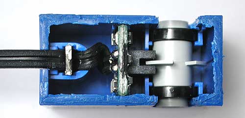
    • the LEGO robot has been built that looks exactly like this one, as is was built using the manual of this particular model:

    • the leJOS Java system has been installed and the sample source code has been taken from the course page

    • the sample code has been uploaded to the robot using USB cable, bluetooth technology does not yet work for us (but we will make effort so it would) Read more about programming and flashing in part 3.1.

    • the robot works fine with the sample source code, it follows the black line successfully oscillating from the black surface to the white via the use of a light sensor. The readouts on the LCD-screen from the lightsensor clearly depicted the amount of light the sensor is picking up, to everyones satisfaction. Read more about our observation of the robot in a environment 3.2.

    • we experimented with the robots behavior by changing the parameter: samplingtime, and making less correction. Read more about tinkering with parameters in 3.3


    3.1.Programming and flashing

    As a part of the first day's agenda, we were to install the lejos system on the NXT brick. This blog posting concentrates on how to get started from scratch, in Debian.

    Overview of the measures taken

    • Permissions and software, host-side

    • lejos firmware upload


    Permissions and needed software

    Everything that has to do with Java is a real pain to get working in a free software environment. Generally, people have written towards the Sun implementation of the language, and that has until recently been non-DFSG. Therefore, Java has had a nasty habit of winding up in the ``contrib'' portion of Debian.

    The software in the lejos PC code is seemingly spread over a spectrum from C to Java. In a bit of a gamble, we've tried using lejos from a free platform, and seemingly succeeded.

    The build process is essentially simple: Download the (NXT!) lejos .tar.gz, untar it, and move the resultant directory somewhere semi-convenient (in the author's case, as a subdir of his homedir). Call that location NXJ_HOME. For the archive, this guide was written using the 0.6 Beta version of lejos.

    The build itself is ant-based (`aptitude install ant`) and simply consists of going to the $NXJ_HOME/build/ directory and running `ant`. This of course requires a working Java compiler (and I'm assuming that more than this was actually also needed). For the author, that was solved using `aptitude install openjdk-6-sdk`, which exists in Debian Sid.

    The nxj compiler (`nxjc`) needs LEJOS_HOME to exist in the environment. Also, the nxj package builds various executables that end up in the bin/ dir, which one may want to have in $PATH. Therefore, to go into NXT programming mode, the following piece of shell code can be sourced (i.e. `source my_nxt_env.sh` or `. my_nxt_env.sh` from a sh-compatible shell). You're smart enough to figure out which parts to customize, yourself.

    #!/bin/sh

    export NXJ_HOME="$HOME/lejos_nxj"
    export PATH="$PATH:$NXJ_HOME/bin"

    After the build and the shell fragment-sourcing, the command `nxjflash` should be available. This however, doesn't run directly out of the box, since it needs write access to the relevant USB device on the host.

    This shows the situation in my system after several reconnects of the NXT brick. Note the rather high last number in the USB identification; this is a consequence of the number incrementing upon reconnection.

    root@moldover,11:03:~# ls -la /dev/bus/usb/00*/*
    crw-rw-r-- 1 root root 189, 0 20080905 11:39:08 /dev/bus/usb/001/001
    crw-rw-r-- 1 root root 189, 128 20080905 11:39:08 /dev/bus/usb/002/001
    crw-rw-r-- 1 root root 189, 151 20080905 11:04:10 /dev/bus/usb/002/024
    crw-rw-r-- 1 root root 189, 256 20080905 11:39:08 /dev/bus/usb/003/001
    crw-rw-r-- 1 root root 189, 257 20080905 11:39:09 /dev/bus/usb/003/002
    crw-rw-r-- 1 root root 189, 258 20080905 11:39:09 /dev/bus/usb/003/003
    crw-rw-r-- 1 root root 189, 384 20080905 11:39:08 /dev/bus/usb/004/001
    crw-rw-r-- 1 root root 189, 512 20080905 11:39:08 /dev/bus/usb/005/001

    As can be seen, all these character devices are owned root:root and chmod'ed so that others than root cannot write to them. This is a problem for using USB programming of the device, since that obviously needs write access.

    The clever way of doing this in a modern Debian system is to use custom udev rules. A sample one is given in $NXJ_HOME/README.html:

    skrewz@moldover,16:14:~/lejos_nxj$ cat /etc/udev/rules.d/70-local-lego-rules
    BUS=="usb", SYSFS{idVendor}=="03eb", GROUP="lego", MODE="0660"
    BUS=="usb", SYSFS{idVendor}=="0694", GROUP="lego", MODE="0660"

    I inserted this, but didn't take the time to make it work (for one because I couldn't be bothered to re-login to effectuate the membership of the mentioned lego group), so running `chmod a+w /dev/bus/usb/002/024` as root (in the above case) was used, to ad-hoc fix the problem.

    Update:
    Well, yeah. One is supposed to insert files into the /etc/udev/rules.d dir, that have names ending in .rules (as opposed to my -rules). When one does that, the above snippet works.


    When the user has gotten write access to the relevant character device, flashing is easy: Just run `nxjflash`. That is, once you find the ``possibly the most well hidden button ever made''.


    Assigning a bluetooth device name and program upload

    On a less important note: One may, with the aforementioned USB access setup, easily run `nxjbrowse`, from where the device name can be set. There's probably a non-GUI way to do this, too. That GUI, however, provides a way to upload files to the unit, too.

    To compile programs, run `nxjc Sourcefile.java`. To upload and run the resultant .class, run `nxj -r Sourcefile`. To do both (which you probably want), sequence the commands with sh's ``&&'' operator.

    Bluetooth connection
    The major obstacle with the bluetooth connection in Debian is to provoke the initial pairing. (isn't that always the problem?)

    In bluez of recent versions, the command-line command is `hcitool cc $addr` with $addr being the colon-delimited MAC address of the device. This will in turn (via sbus, I believe) prompt the user's selected GUI for a passphrase. For my part, that GUI is kbluetooth, which is an annoying resource hog to have running for that purpose alone. However, the skeletal key-agent provided with bluez is of little use in day-to-day use. It is however important to notice that it is needed to have a such agent running, because generally, the pairing is strictly interactive.

    It is a flaw that the NXT brick uses a default passphrase in the bluetooth pairing, when it could easily read-out a value and require the authenticated user to enter the randomly generated value, that is displayed in the NXT's display. For bluetooth mice, this is excusable, but even bluetooth keyboards should pair using a non-hardwired value of the passphrase.

    3.2.Observation made of the environments effect on the system

    When finally we got the bad boy to work, it was with the standard code of the assignment; the linefollower program. Right away it was tested on a small curvy course.
    The first thing to noticed was, it works. The second thing to noticed was, it isn't a line follower, but rather a follow-the-course-in-such-a-way-that-you-have-dark-surface-to-the-left-of-you,-and-bright-surface-the-right. The program works by correction the robots direction for every control-loop. The philosophy is: Vary to one side of the threshold, do this, vary to the other side, do the opposite. This makes the controlsystem a Bang-bang controlsystem.

    The fact that the software only works by asking, and acting on a binary question: "Does the sensor measure above or below the threshold", and that the physic's of the system only is one sensor measuring light-reflection right below it, the environment has a great effect on the system. As mentioned, the robot worked right away, oscillating from black to white underlay. But move it to the other side of the black line, so that white surface is to the left, and black to the right, the robot starts to go in circles. This was of course because the software relied so heavily on the fact, that when reading white-surface, black-surface is to you left -- so turn left. That, when put in a situation with white surface to the left and black to the right, the algorithm compensates in the wrong direction.

    That being said, this approach was very efficient at following the curved course, because the robot just would keep on turning the same way until the threshold was surpassed, effectively dealing with any king of curve the track threw at it. The robot made the course with at fairly good time.

    3.3.Different parameters influence on the system

    The first parameter we tried having fun with, was the sampling time. Initial thoughts: smaller samples intervals -- quicker advance through the curse. This hypothesis turned out to be true.
    But first we sat the sample intervals up, by changing "Thread.sleep(100)" to "Thread.sleep(1000)". As an effect the algorithm was destroyed. The sampling time was so low, that coming from white underlay the robot could surpass the black, and get a "white surface underneath, so you better turn left!"-reading, resulting in the robot starting to turn in circles.
    As predicted, when "Thread.sleep(100)" was changed to "Thread.sleep(10)", the robot did go faster forward. The reason for this is that faster reading result in quicker correction of which way to turn, resulting in greater parts of the circular motion of turning to be converted into movement forward.

    With the next parameter we had some fun with was the K-factor of the error-correcting algorithm. Instead of only operating one motor at a time -- operate one of the motor on full- and the other at half- capacity. This vastly increased the speed of the robot through the course. As an effect, it also made the difference between quick-sampling and normal-sampling less significant. All tho the fastest way around the course was with quick-sampling and both motors "on" at all time, combining them didn't give double the speedup.

    4. Conclusion

    The starting sample program with the sample robot worked great. It was interesting to make some experiments and see how differently the robot behaves. We will try to figure out how to work with bluetooth and apart from that we eagerly wait for next assignment.

    Preparations

    Installing relevant stuff and playing with LEGO bricks.